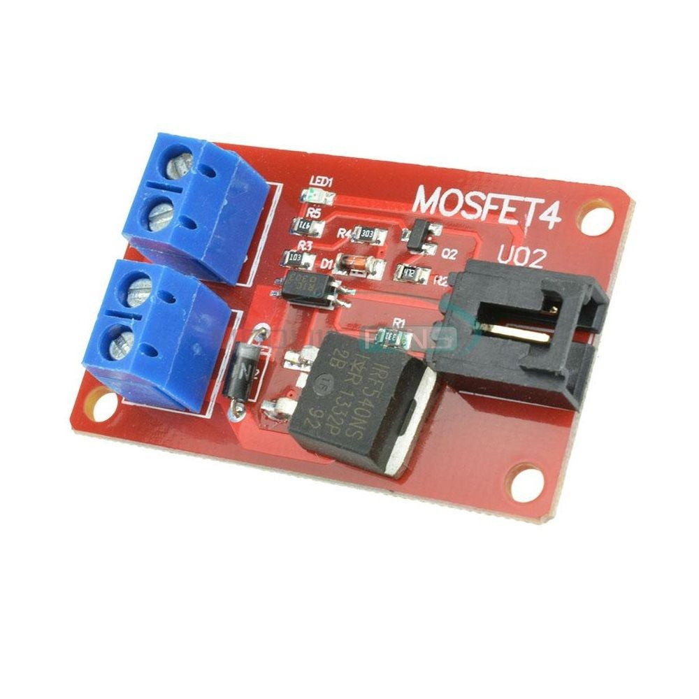
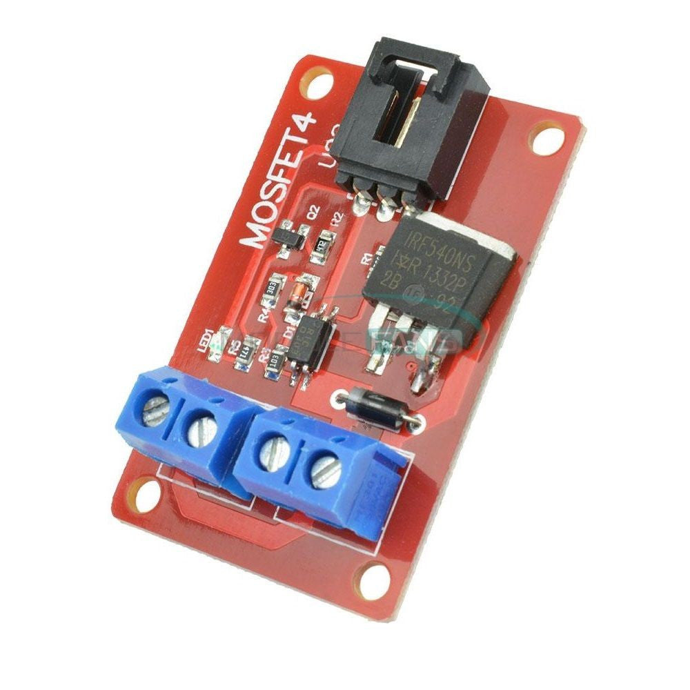
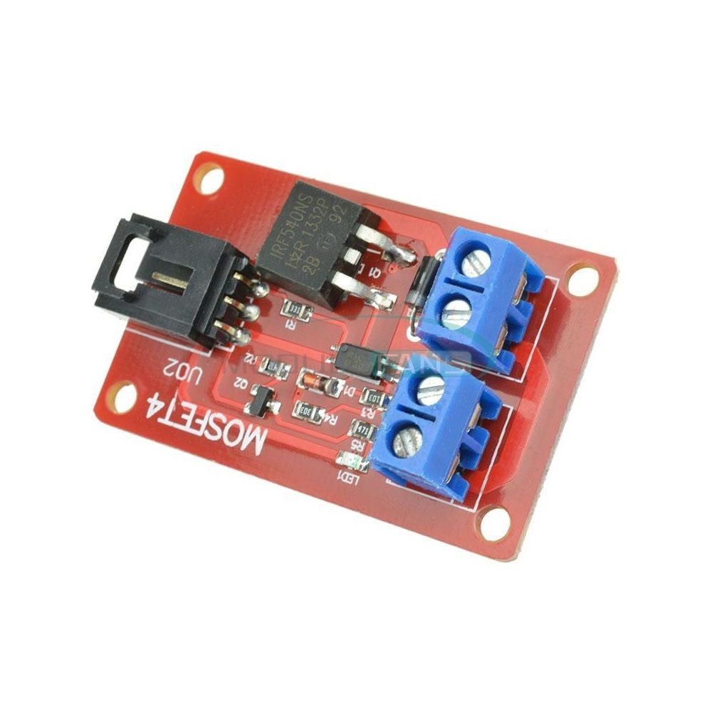
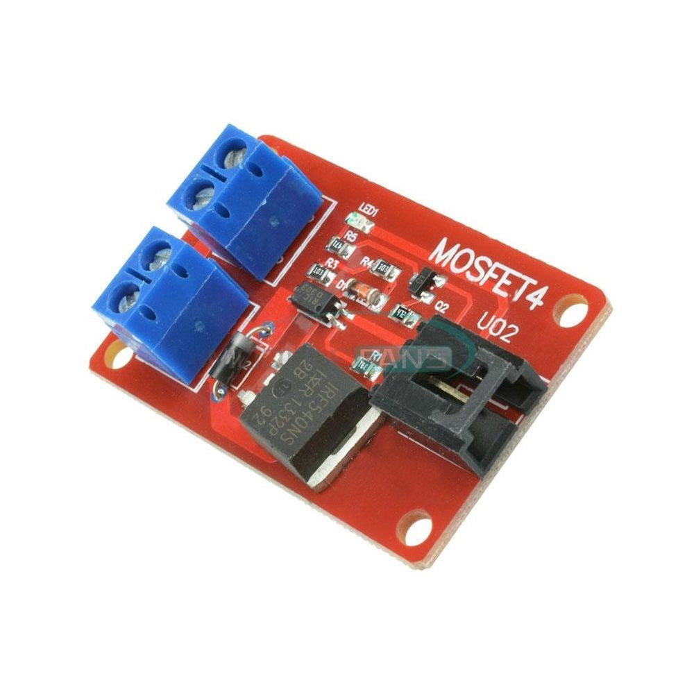
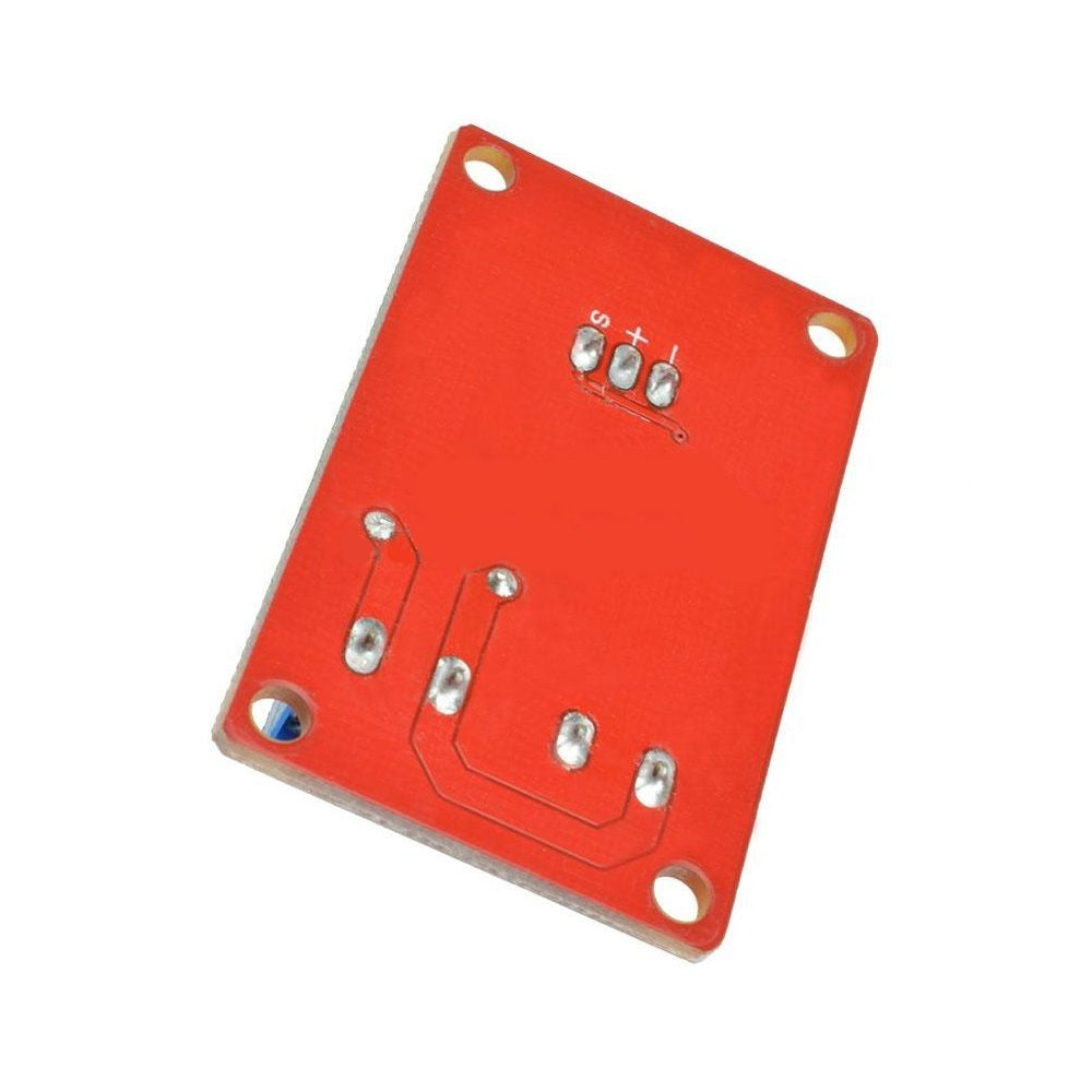
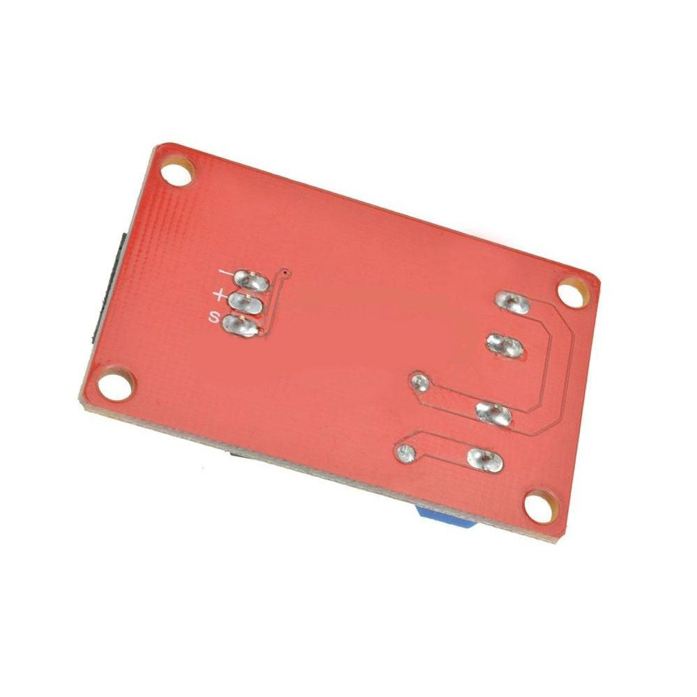
1 Channel 1 Route MOSFET Button IRF540 + MOSFET Switch Module for Arduino Pi
£4.50
1 Channel 1 Route MOSFET Button IRF540 + MOSFET Switch Module for Arduino Pi
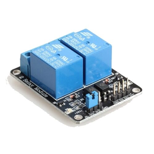
MOSFET is an electronic device having a good switching characteristics, is widely used in the electronic switch circuit needs, such as switching power supplies and motor drives, and a lighting dimming. Relays are all very familiar with another module has switching characteristics, but because of the working principle of the relay is generally achieved by mechanical contact on and off purposes, which will inevitably lead to a very short switching times under the circumstances, the relay situation does not work, the other sounds when Baba contact switch in some cases is more annoying thing.
Use this module with for for arduino electronic building blocks 4 IRF540 MOSFET switches use the same, but changes to the way the original four. Use reference for for arduino 4-way switch IRF540 MOSFET Modules:
We designed this four-way MOSFET switch can provide up to four groups of electronic switches, were used to control different circuit modules. Affected MOSFET works, the electronic building blocks can be used to control the DC circuit, such as DC LED screen, etc., are not suitable for controlling the AC circuit. Under extreme circumstances of the MOSFET switch can be used to control 100V / 33A DC circuit, but control is recommended not less than the minimum DC voltage 9V.
The circuit is connected at one end of the wire is slightly controlled some trouble. To control a 12V LED lights, for example,
First, the positive (+) and negative (-) between the connected power;
Then connect the positive LED lights with the module connected to the positive (+),
LED lights with the anode connected to the switch 1 (S1) on;
If there are other LED lights with the need to control,
Just the same cathode lights with LED module is connected to the positive (+),
LED lights with the negative electrode in turn is connected to the switch 2 (S2), switch 3 (S3), the switch 4 (S4) on;
Connection control side is much simpler,
We only need a sensor cable,
The corresponding control port for arduino sensor expansion board connected, you can control the 12V LED lights brought by for arduino.
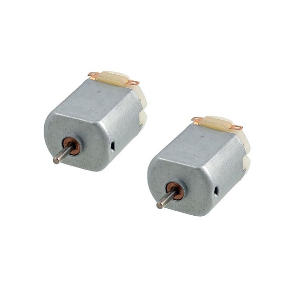
Experiment, we picked up two LED lights.
Test code as follows:
int s1Pin = 6;
int s2Pin = 7;
void setup() {
pinMode(s1Pin, OUTPUT);
pinMode(s2Pin, OUTPUT);
}
void loop() {
int i;
digitalWrite(s1Pin, HIGH);
digitalWrite(s2Pin, HIGH);
delay(500);
digitalWrite(s1Pin, LOW);
digitalWrite(s2Pin, LOW);
delay(500);
for (i = 0; i < 10; i ++) {
digitalWrite(s1Pin, HIGH);
delay(500);
digitalWrite(s1Pin, LOW);
delay(500);
}
for (i = 0; i < 100; i ++) {
digitalWrite(s2Pin, HIGH);
delay(50);
digitalWrite(s2Pin, LOW);
delay(50);
}
}
Package Content:
1 x 1 x 1 Channel 1 Route MOSFET Button IRF540 + MOSFET Switch Module
Raspberry Pi is a Trademark of the Raspberry Pi Foundation
Product ID: EP00384